Game Frame
For the game frame, it consists of two frames and spacers in between them. The wood used was two inches long and one and a half inch thick. The bottom frame uses of two 3 ft pieces of wood and two 10.5 in. ft pieces of wood. The two 10.5 in. pieces of woods should be placed between the 3 ft pieces of wood and screwed together with two screws on each side. For the top frame the setup is the same as the bottom one. The front spacers should both be 4" inches high. The top of these spacers should be sanded down at an angle that will allow the front height to be 8" inches total. The back spacers should each be 8" inches and also be sanded down to allow the back height to be 12" inches. There should be screws that are screwed in diagonally as shown in Figures 1 and 2. The placement of screws in Figure 2 applies to the back of the frame as well. Figure 3 shows how the pinball machine should look once it has been constructed.


Figure 3: Actual finished Game Frame
Side Plating
For all of the side plating the game frame was used to trace out the piece of plywood that will is cut. Using a half inch plywood, place the wood against the game frame created or using the information needed to create the game frame, trace out the front, sides and bottom. The back should be cut out but not drilled to the actual machine due to the fact that that open space will be needed order to place the sensors and other electrical parts. Using woodworking tools, cut out the plywood shapes and drill them to the game frame.
 |
| Figure 4: Frame with bottom, side and front plating |
Backboard Frame
For the backboard frame, 4 two and a half feet (2 by 1 1/2 inch) wood pieces are needed. Two will be used for each side. 6 four inches wood pieces (same type) will be needed. These will be used as the spacers in between the 2 1/2 feet pieces of wood. Figure 5 shows the where the screws should be drilled in and where the game frame is so that it's placed correctly. Based on the figure, the game frame should be on the left side of the backboard frame. Figure 4 shows an actual picture of the assembly of the backboard frame. |
| Figure 5: Side View of Backboard Frame with screw placement |
Backboard Plating
For the backboard plating, the sides, bottom and back need to be traced and cut out. The bottom piece of plywood is 7 by 23 inches, the back is 23 by 30 inches, and the sides are 7 by 30 inches. The bottom and the back should be drilled onto the machine. Do not drill the side plating. The extra space is needed in order for the setup and wiring of the display. 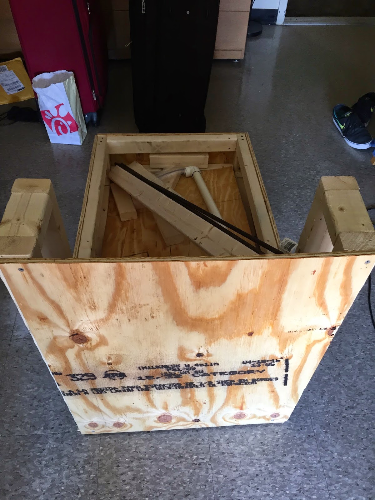
 |
| Figure 6: Pictures of pinball machine with backboard frame and it's plating |
Playing Field
The playing field is made of the same material as the siding on the machine. The actual dimensions for the board that we used was 32x15 inches. In order to create the slope so that the ball will roll down, nails were drilled through the sides of the machine at two different heights for preferred steepness. Make sure the board is not bigger than the interior dimensions of the game frame. If it is then the playing field will not fit inside the machine. |
| Figure 7: Shows nails drilled in side of machine for incline of playing field |
Flipper Mechanism
For the flipper mechanisms, a website site was used to make the basic design and then it was tweaked a little for the actual machine. This link will allow you to go to the webpage that has the steps to make the flippers. There are some differences in the website's design and this project. |
| Figure 8: Websites design |
 |
| Figure 9: Project's Design |
The differences between them are that instead of going to the bottom of the machine, the stoppers on the project go to two pieces of wood that have a hole and pathway for the ball to go to the ramp. Also three pieces of wood have been place in order to make sure the rod doesn't move in the wrong direction and cause the flippers to malfunction.
No comments:
Post a Comment